Excess 3 Adder Circuit Diagram
Solved 4. (a) construct a 4-bit binary adderisubtractor Excess 3 adder circuit diagram Excess 3 addition by parallel adder, combinational circuit in digital
Excess 3 Adder Circuit Diagram
Bcd adder schematic diagram Adder excess binary construct bcd 4 bit bcd circuit diagram
Explain four-bit parallel adders with block diagram, and also explain
4 bit adder subtractor circuit diagramAdder excess subtractor 8 bit full adder circuit diagramExcess 3 adder circuit diagram.
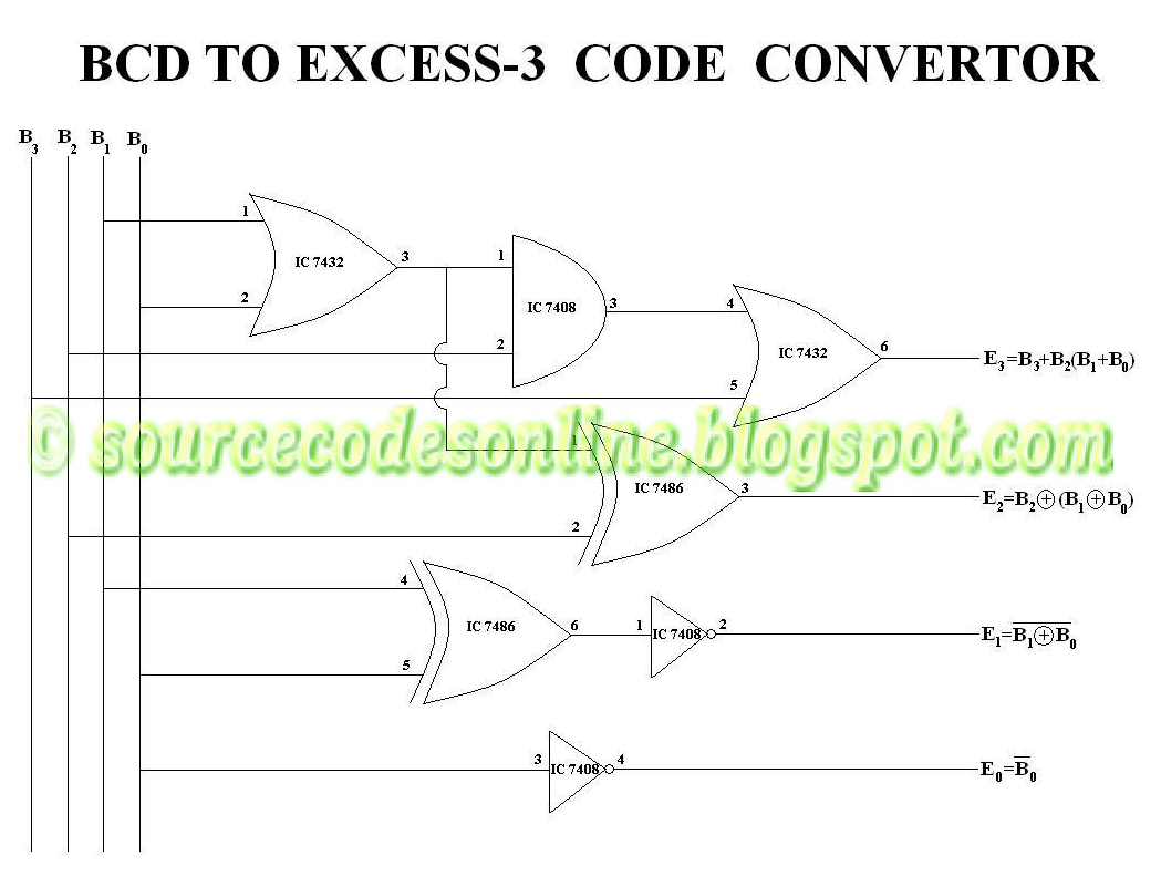
Bcd excess converter code circuit logic digitalBcd to excess 3 code converter digital logic circuit design download Make half and full adder without chipsExcess bcd code circuit logic 8421 digital converters geeksforgeeks.

Bcd to binary converter circuit diagram
Excess 3 adder circuit diagramExcess 3 adder circuit diagram Excess 3 adder circuit diagramBcd to excess 3 code conversion » freak engineer.
Full adder equationDigital logic Excess-3 adder subtractorExcess 3 adder circuit diagram.
![[DIAGRAM] Bcd Adder Circuit Diagram - MYDIAGRAM.ONLINE](https://i2.wp.com/www.researchgate.net/profile/Saman_Amarasinghe/publication/37595015/figure/fig7/AS:309873876193289@1450891097709/Full-Adder-Circuit-Diagram.png)
4-bit adder subtractor
Excess bcdAdder circuit truth logic xor sum adders gates ripple schematic binary theorycircuit rangkaian circuits transistor schematics dan pengertian kombinasi equation Empower youthLab 009 bcd to excess-3 code.
How to build a full adder[diagram] bcd adder circuit diagram Adder circuit truth logic gates binary circuits introduction equationsExcess 3 adder circuit diagram.
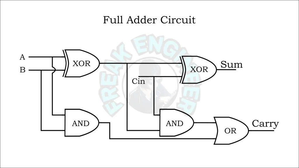
Full adder circuit and its construction
Solved design an excess-3 adder circuit that adds two validBcd to excess 3 code converter using nand gates(project) ece419 digital Excess 3 adder circuit diagram[diagram] bcd to excess 3 logic diagram.
Full adder circuit – how it works .


![[DIAGRAM] Bcd To Excess 3 Logic Diagram - MYDIAGRAM.ONLINE](https://i2.wp.com/www.deldsim.com/circuit_diagram/39.png)

